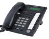
Panasonic KX-TA824 EZ Installation
Do It Your-Self Installation
E System Sales, Inc. offers services by phone to help you with your Panasonic KX-T Installation. A do-it-your-selfer can perform a Panasonic KX-T installation if the KX-T Installation cable and block kit is purchased. Please follow these instructions as well as your Installation CD which your will receive with your Panasonic Telephone Equipment
Do-it-yourself installation. The Panasonic KX-T Installation cable and block kit helps when installing the Panasonic KX-TA824. All Panasonic phone systems KX-T are plug and play. You will be ready to send and receive phone calls.
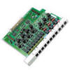
NOTE: 1 pair of wires is required on all incoming phone lines and 2 wires is required on all phone extensions. A 66 Block termination punch down tool is also required for installation.
Punch down the appropriate pair of wires for each terminal. For example, the 101R, 101T, 101P& 101G terminals are the terminals for the first phone extension which is extension 101, and the Line 1R and the Line 1T terminals are for the first incoming telco line witch is Line 1.
Panasonic KX-TA824 Punch Down Block Schematic

|
RJ61X |
66 Block |
||
|
Block Term |
Color Code |
Function |
|
|
Cable |
1 |
White-Blue |
101 T |
|
Cable |
9 |
White-Blue |
103 T |
|
Cable |
17 |
White-Blue |
105 T |
|
Cable |
25 |
White-Blue |
107 T |
|
Cable |
33 |
White-Blue |
Line 1 Tip |
|
Cable |
41 |
White-Blue |
Un Used |
The above diagram is a schematic view of the telco 66 Block provided in the installation kit. Click here for a exploded view of a 66-Block. The installer will notice that there are 2 empty terminals on the bottom of the 66 Block. That is normal.
|
Take your telephone but set.
Individually plug the two Alligator clips on to each pair of color coded (white/Blue blue/white) wires. Locating wire pairs for telephone connections.
Plug the tone generator into |
Take the Alligator clipsListen for dial tone, if dial tone exists call your Cell phone and check the caller IP LCD screen to check the phone number you have dialed from.
In the phone room or distribution facility run the tone amplifier along each of the connector punch down interface on the 66 Punch Down Block until you hear the tone at to its loudest point over two of the conductors and you have found the pair of wires foe the phone on the office jack in question. |